Last night (Monday 4th October) LAMM was able to hold its first AGM in twenty months. Our rules state that the AGMs are an in-person affair with a set number of attendees needed to achieve quorum, and although we could have used on-line event conferencing during the lockdowns we held the physical meeting for a period when we could be truly in person.
As part of that meeting I prepared and gave a report, more a round up, from the board to the members. LAMM tries to be as transparent an organisation as possible, and in that light I present that report for distribution via our blog.
Report from the Board 4th October 2021
I wanted to start today with some meaningful quote, Like ‘it was the best of times, it was the worst of times’. However, to be honest, it’s been mostly just awful and we still seemed to be mired within issues so let’s skip that.
So while I quit moping I want to welcome you back to LAMM and our AGM. During the last twenty months since our last meeting you would think that life at LAMM would have been quiet. But we did not let a global pandemic and political upheaval stop us from showing how good a community we can be. Which allows me to segway into my first thanks.
I want to thank all the members who have stayed with us through these challenging years. I also want to especially thank those who were able to keep up payments. This in no way is meant to disregard those who could not manage, everyone had their own fiscal circumstances to navigate. But, those of you that were able to keep paying your fees kept LAMM alive. So you have the deepest regard and warmest thanks from the Board.
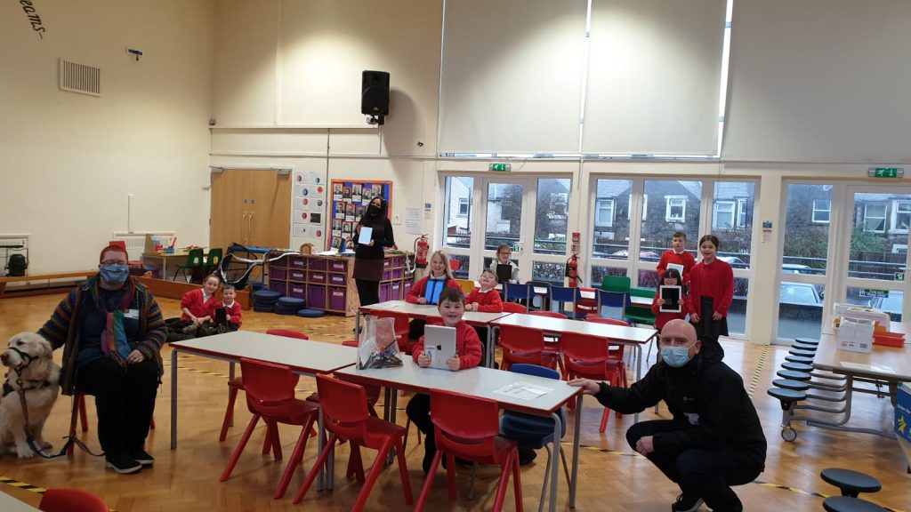
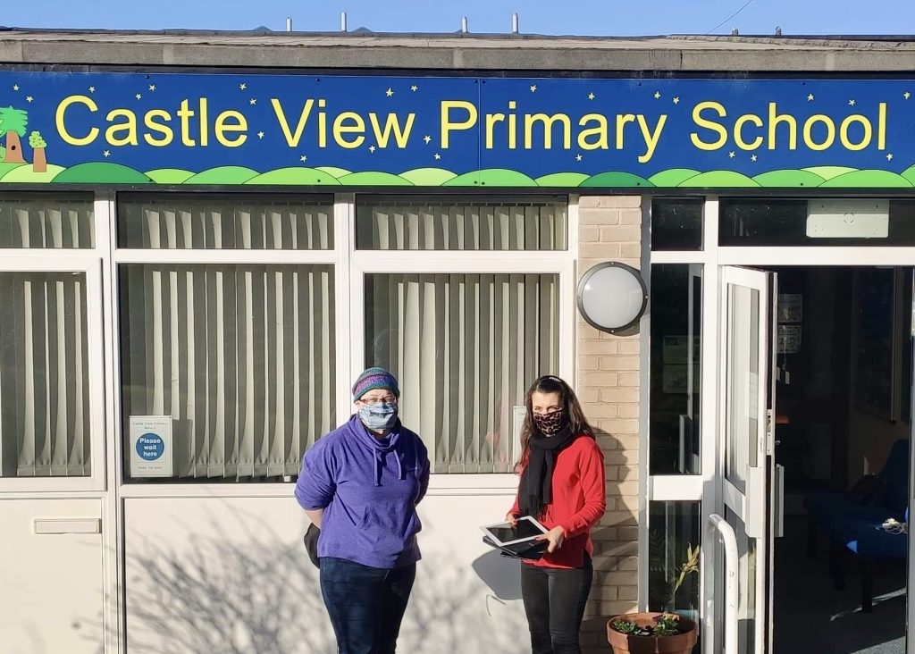
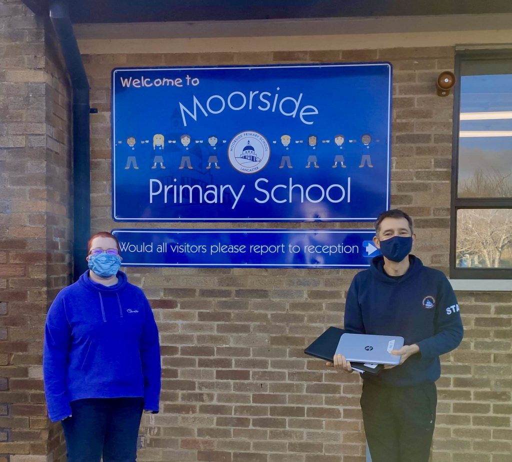
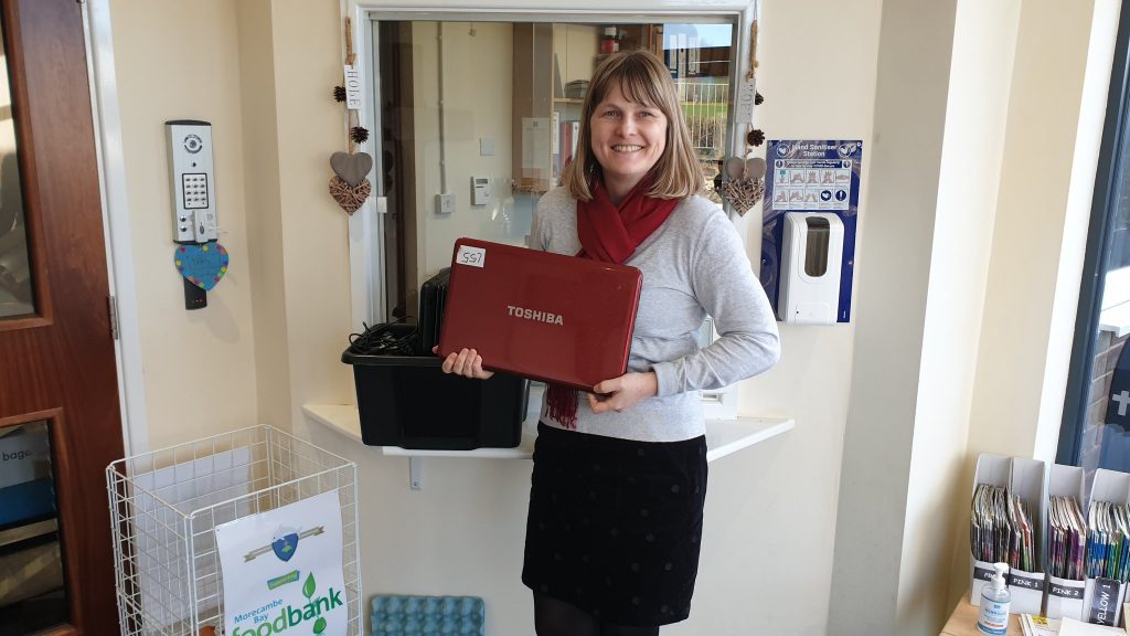
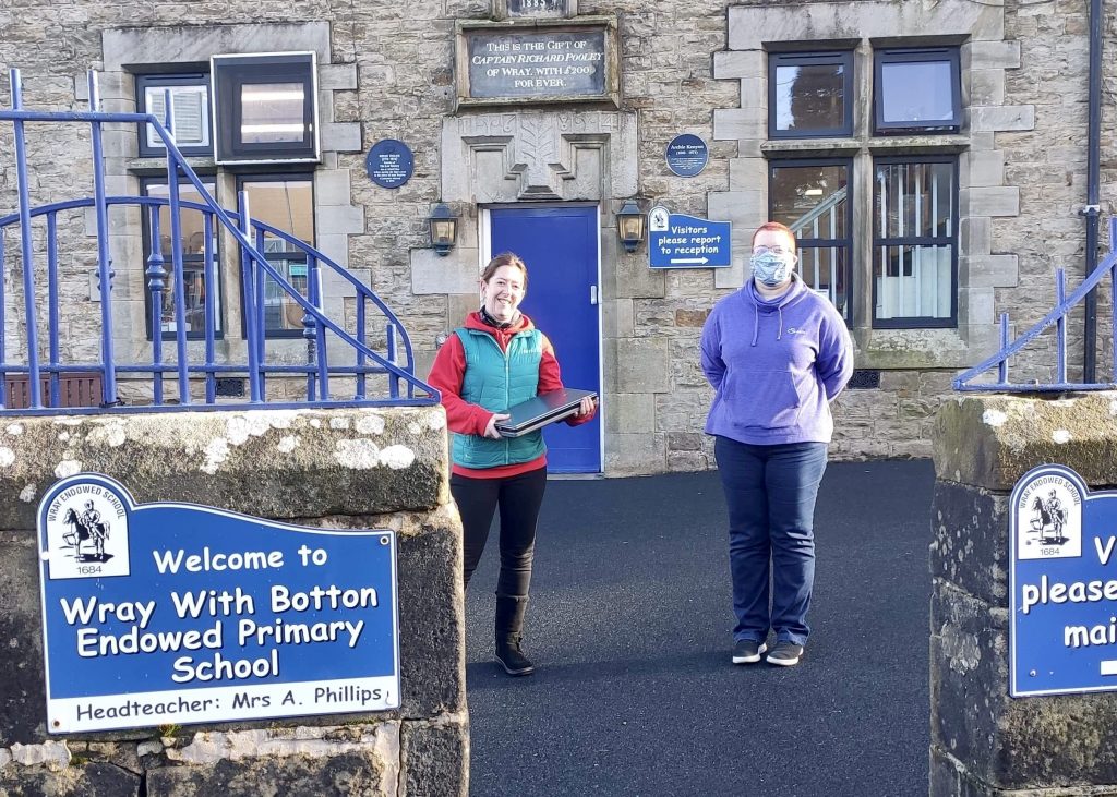
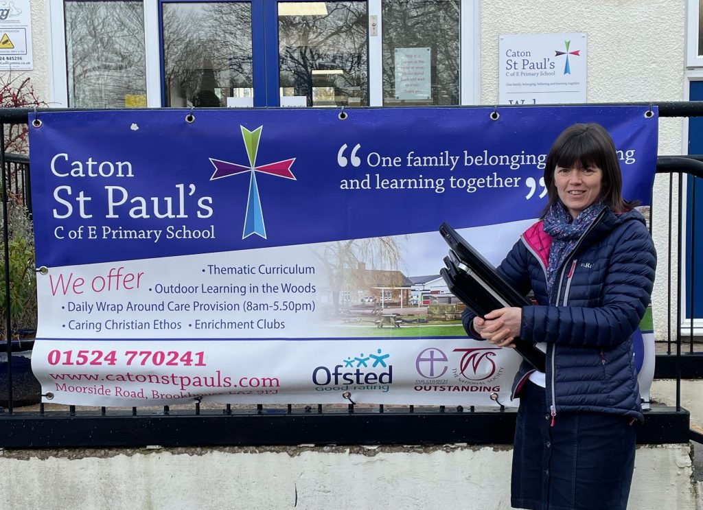
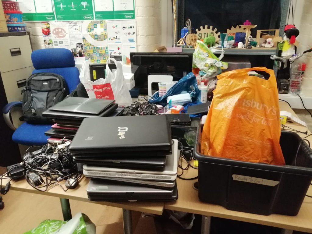
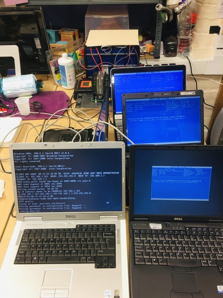
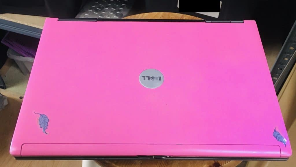
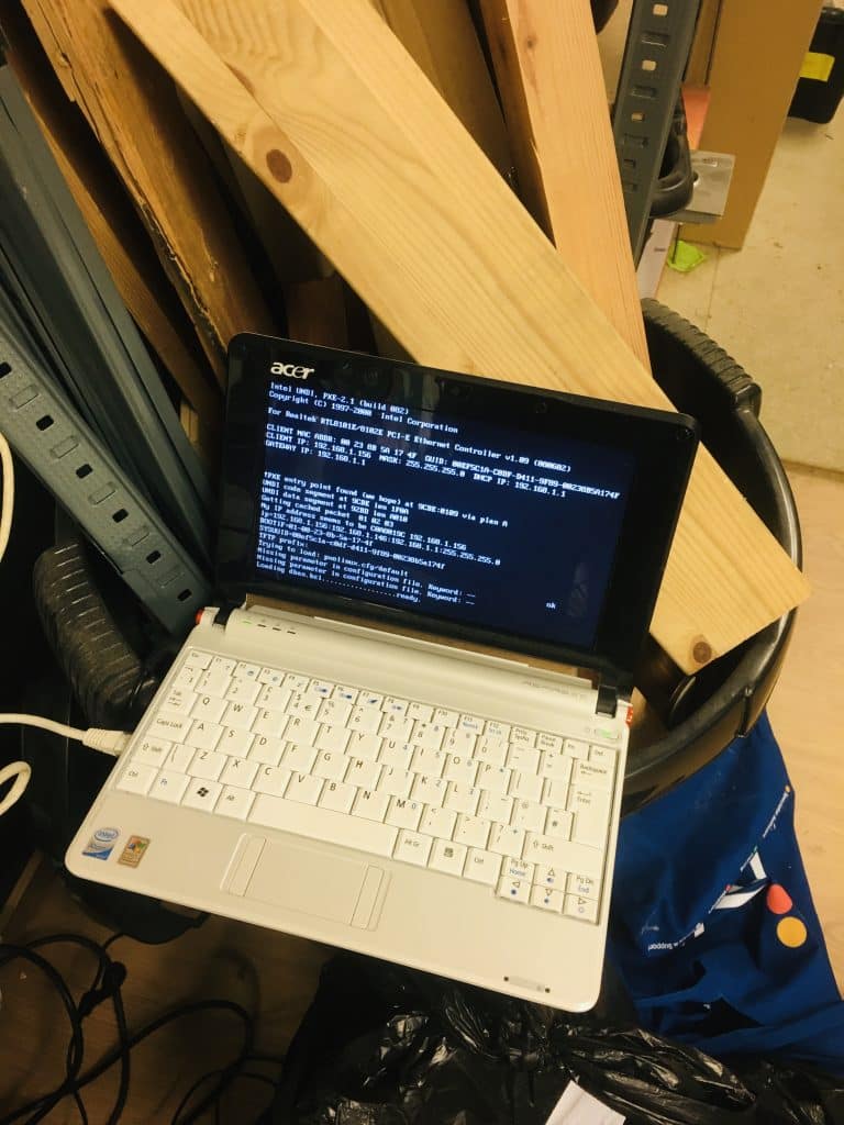
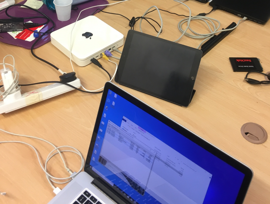
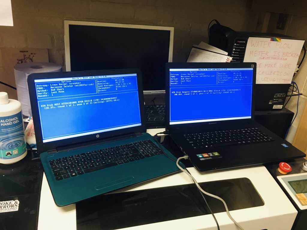
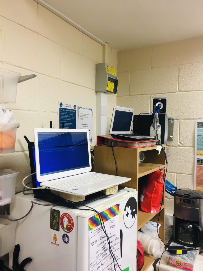
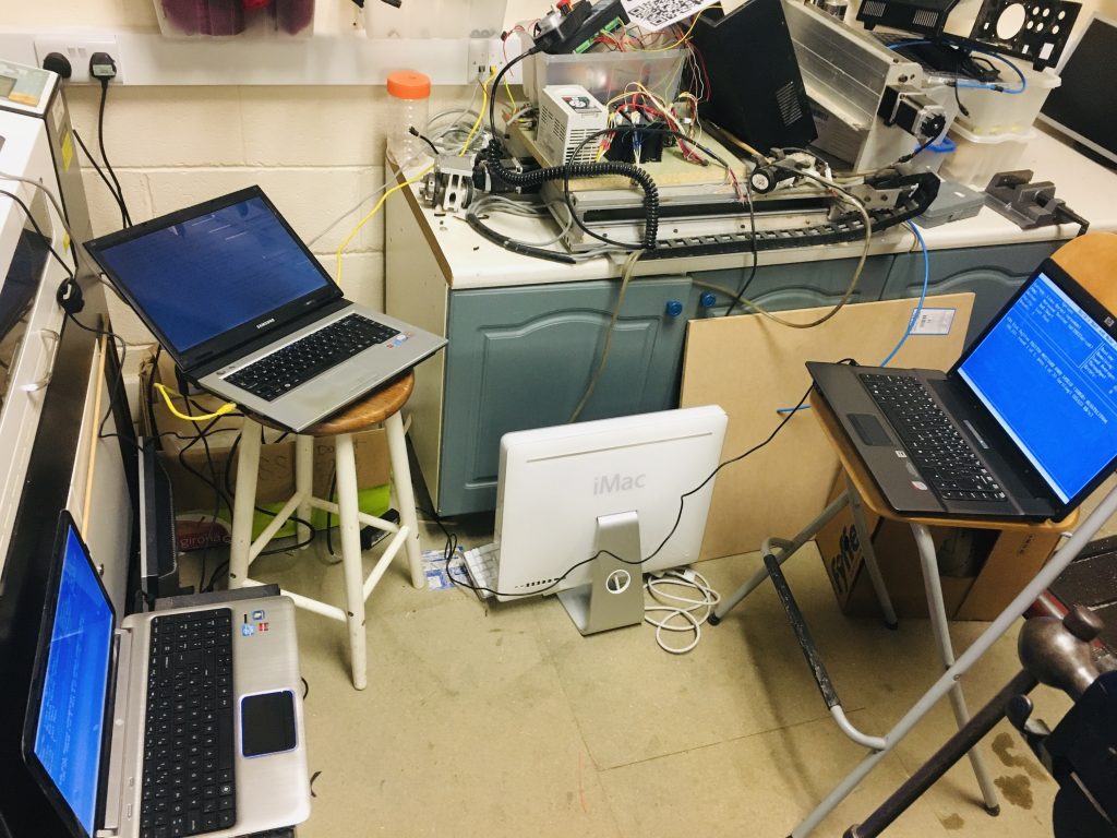
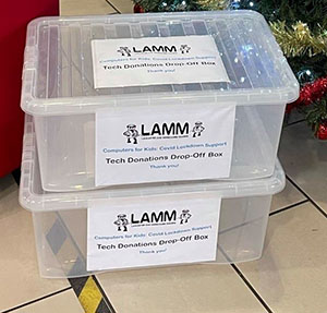
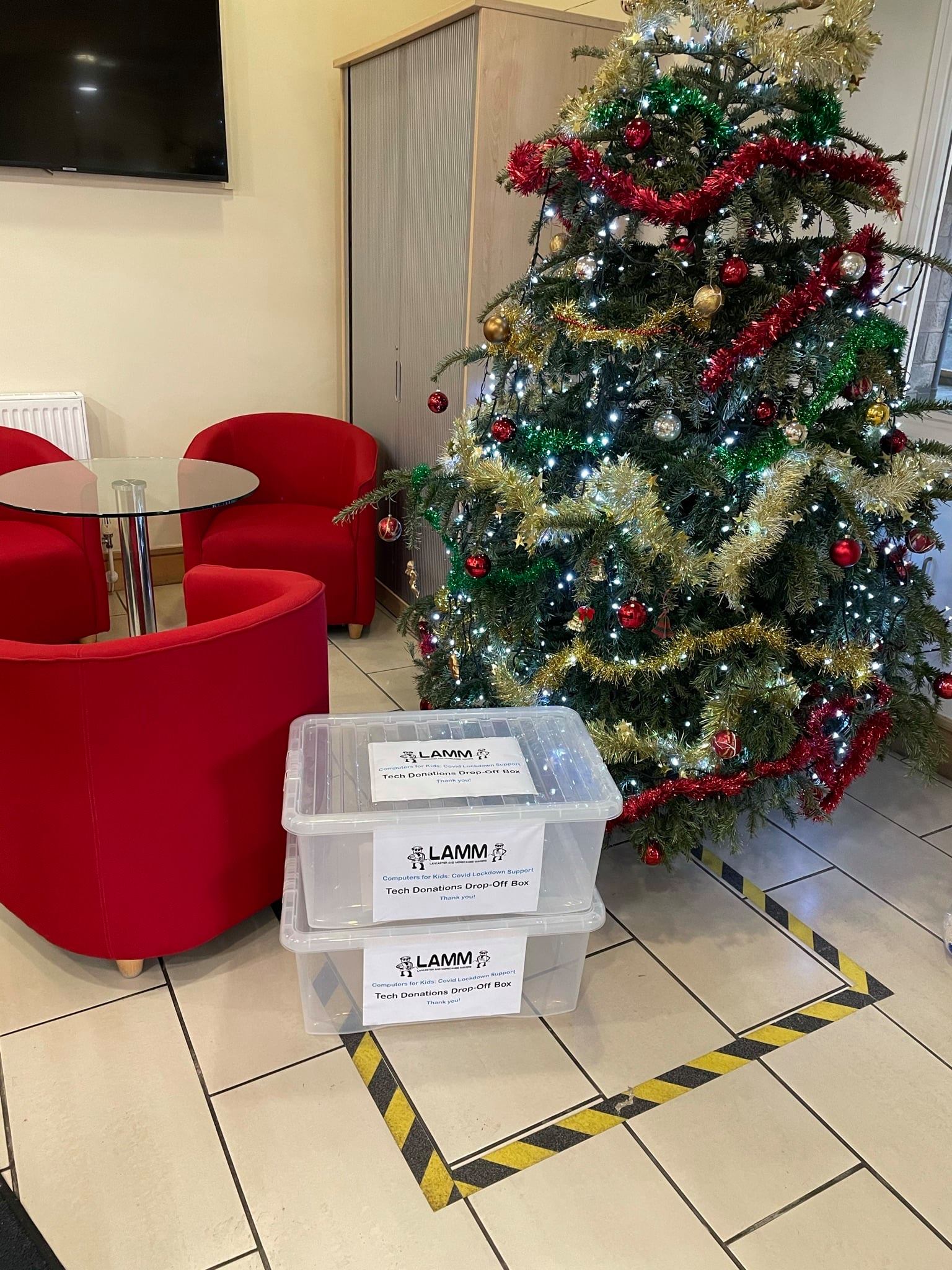
My second thanks goes to those who ran a successful campaign to get laptop and devices into schools and into the community. We had several hundred donated machines and over one hundred and fifty of these were repurposed for Schools. A further batch were given to those that are disadvantaged members of the wider community. You have our respect and grateful thanks. The continuing project will carry on as we hope to build on that in the future.
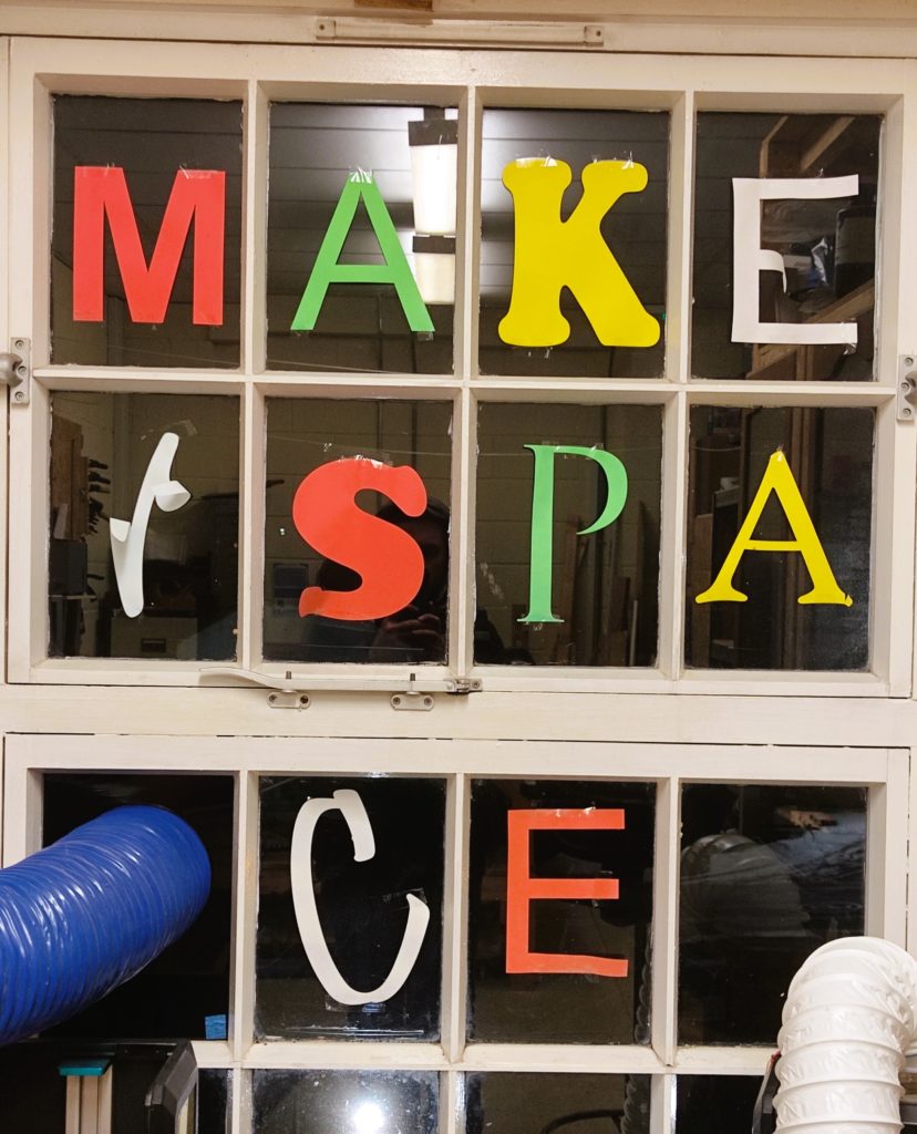
LAMM has moved in the last six weeks. We now have a bigger Space, SPACE 2, or Space Squared or Space to do. Whatever you want it to mean. A lot of you gave your time, your strength and mostly everyone gave their positivity to the effort. It has been greatly appreciated and the new Space is already looking great and we look forward to completing the organisation, bringing tools back online in readiness for re-opening to the general public. All members are welcome back into the Space and we’d appreciate any suggestions. Bil has already built a new moveable wood store. So that is my third thanks.
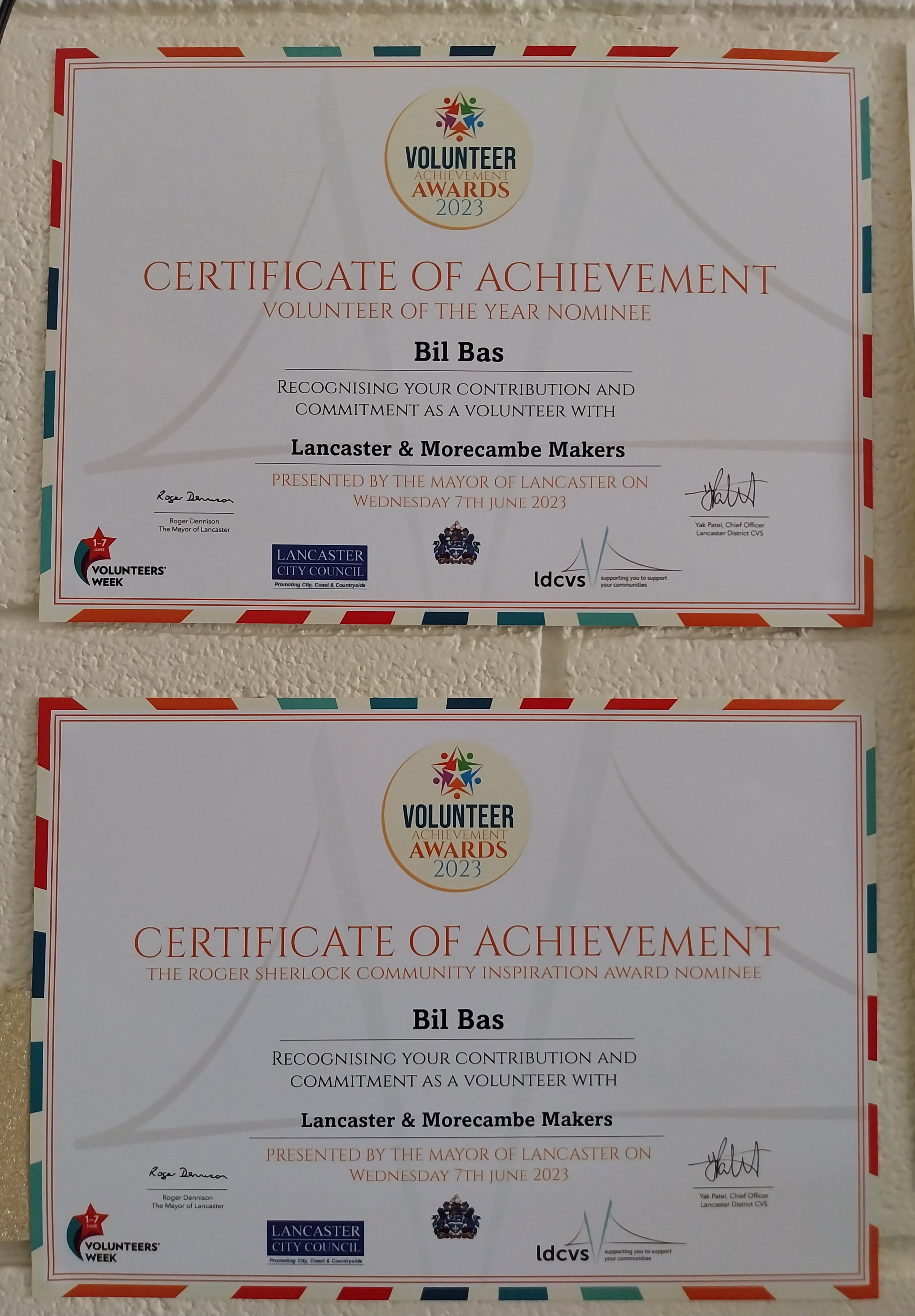
Lastly I want to single out Bil who also ran our first outside event post-pandemic last weekend at the Fun Palace. He once again engaged with young people and the wider community and had them destroying laptops. Every effort is appreciated and the board are grateful that we have a membership who are willing to get involved, organise and run events.
To the future we look to you. Hopefully we will now have more face to face contact. I encourage you all to use the Telegram channel and notice boards (when it is put up) to leave messages and suggestions and I dearly hope that we can all start to get our own projects completed. But we also need to grow our numbers and show what a great community workshop we can be. In the coming year we hope to form alliances and cooperative projects with other groups and with local academic institutions.
Finally, I want to say something personal from me. Not from the board. I want to share a fear. I worried at the start of the lockdowns. I felt that this may end our organisation. We would struggle to survive and this left me feeling helpless. But we have come through, we have contributed to a positive change in our local community and we are now in a stronger position to grow. So thank you all.
LAMM is very dear to me and to see it not only survive but become greater has been a very bright light in what has been a dismal time.
So you all have my personal thanks.