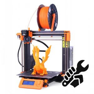
We recently decided that we needed a new 3D printer for the space, given that one of the members who had been kindly lending us their printer (thanks Vic Harkness) has moved away, and the other main printer we have, which is also lent by a member, is currently not working. We’ve had several people joining recently because they wanted to do 3D printing, so we decided it was important to have a printer that was owned by the space, which we could maintain collectively. We settled on a kit of the Prusa i3 printer from prusa3d.com (see image, which is copied from their site).
The box arrived just in time for our Wednesday open meeting last week, and was eagerly unpacked. As several other blog posts I’ve read have said, it was immediately obvious that a lot of care had gone into the design and also the packing of this kit. The outer box was pretty substantial and all the parts were well organised and neatly packed inside smaller boxes. The 3D printed parts and smaller fixings were put in plastic bags labelled by the assembly they belonged to, which makes it easy to work through the assembly manual and know that you have all the parts for the current step to hand. There were even screen printed labels on the motors to say which axis they belonged to.
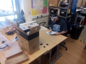
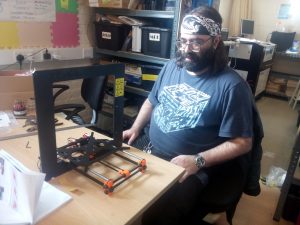
Due to peoples’ time commitments, we had to wait until Monday morning to make a start on building the printer. The building was done by Gustavo Carreno and Andrew Baxter.
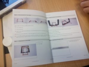
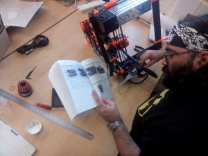
The assembly manual was pretty clear and helpful, with colour coded photos of the tools needed and the 3D printed parts used in each step. The online version is also useful if you can’t make out the details in some of the pictures.
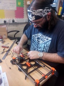
The main thing to say about the build process, apart from a few small points I’ll make later, is that it’s pretty much just a question of preparing yourself for a number of hours of careful assembly work, following the instructions step by step. (We did it over 3 days, but two of them were half days. Some people have done it in an afternoon, but expect to take longer if you’ve not built a printer before). None of the steps are that difficult in themselves – you just need to keep paying attention to what you’re doing. I would suggest that it might be worth at least skim-reading through the instructions for each stage of the assembly before you work though and build that stage, just to get an idea of where you’re going with it. However we mostly just worked through in order and didn’t have any real problems.
One thing that we did a bit differently from the manual, which I think is worth passing on, was to do with aligning the y-axis stage. If you look at the assembly manual, on page 6 of the version I have, under ‘Step 6 – Fully assemble the Y-axis stage’, it points out that it’s important to get the axis perfectly rectangular at this point, or you’ll have trouble calibrating later. One thing here is that it’s probably better to get a reasonable alignment here, but wait until a few steps further on before you really try to get it precise. This is because in the following steps you will be fitting the stage to the main frame, and also to the smooth rods that carry the Y-carriage, so some of the dimensions may need to be changed.
Another thing is that the automatic calibration process is actually pretty good, at least at aligning the X and Y axes, so the kit should be reasonably forgiving of small alignment errors. In other words don’t do what we did and spend a whole morning trying to get the Y-stage perfectly aligned, only to discover that (a) as I’ve said above we then needed to change things again, and (b) the automatic calibration takes out most small errors anyway!
You might also like to try the following trick for getting the frame rectangular and level. Do this after you’ve fitted the length of the carriage to the 8mm smooth rods, as in step 10, but skip step 9 (‘tighten the sides to the y-axis stage’) for now. In other words, at this point you should have fully assembled the Y-axis stage, and adjusted the length of it to the smooth rods.
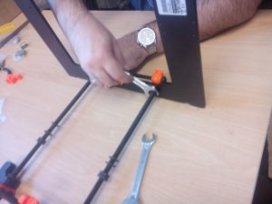
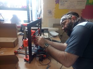
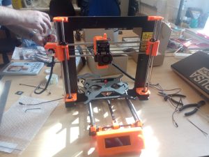
What we did next was to start by loosening all the M8 nuts on the Y-axis stage, so that it could adjust in width (but not length) to fit the main frame. Next we slid the front end of the stage into the slots in the frame, setting the width. Then, which is what is different from in the manual, we moved two of the loose M10 nuts which will eventually hold the frame in its final position all the way down the threaded rod until they could be used to clamp onto the frame, and used a spanner to tighten them, as shown in the picture above. The idea was that with the M8 nuts still loose, this would force the two M10 rods to be close to perpendicular with the frame and thus make the stage rectangular. Then at this point we carefully tightened all the M8 nuts.
Finally we took the Y-axis stage out of the frame and used a ruler to check all of the widthways and lengthways dimensions at each end, and made final adjustments as appropriate. Whether this is better than what the manual suggests, I’m not sure, but we did okay when it came to running the automatic calibration.
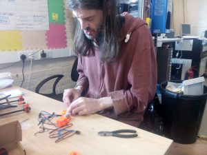
The X and Z axis assemblies were pretty straightforward – as I said above just a case of working through the instructions carefully. Tightening the X (and Y) axis belts was a little bit tricky – the knack seems to be to make a loop of about the right length held in a pair of pliers, then keep trying it against the belt holder and if it’s too loose, keep moving it tighter one tooth at a time and trying it again.
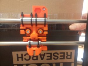
Don’t do what we did and forget you can slide the whole X-axis down along the Z-axis to get to the back of the X-carriage and work on the belt. You might also like to pause at this point and admire the skull-like appearance of the back of the X-carriage!
The extruder was also pretty straightforward to assemble. Managing all the cables going from the extruder to the electronics was tricky, but we did all right following the instructions step by step. Using a piece of 3mm filament to stiffen the cable bundle is a neat trick.
After the extruder, it was time for the LCD assembly. The main thing here was to be careful not to crack the circuit board of the LCD while getting it into the plastic frame.
Next was the power supply and heated bed.
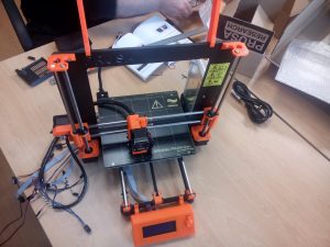
Finally, it was time to wire it all up – the electronics assembly. One difficulty here was that because all the parts on the electronics housing are black, it was hard to make out what is what in the printed photos. The online manual is useful here. Getting all the cables to the right place needs a bit of care, as many of them take the same fittings. However if you just follow the manual and double check each stage of the assembly you should be okay.
Finally, after 3 days work, on and off, we had a fully assembled printer. At this point, we had to break while I (Andy) went to an un-missable appointment and had lunch. Gus chivalrously waited for me to get back before we did the grand turn on.
Somewhat to our surprise (mine anyway), it passed all its tests first time. The calibration took a while but went all right (although the first time we did it, the printer seemed to lose the settings when we turned it off and we had to re-calibrate). It was interesting to see how it first scanned roughly around the points where the calibration markers were, and then homed in on them more precisely.
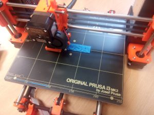
Then it was time to do the first print. There are several prints on the SD card that comes with the printer – we chose the Prusa logo, which came out nicely.
I don’t want to spend too much time on a review of how the printer works – this post is meant more as a guide to the build process rather than a review. Maybe one of us can do a review of the printer when we have a bit more experience using it. However, my first impressions are very positive. The prints are as good as or better than the Lulzbot TAZ we were using before, the calibration system is very neat indeed, and the LCD controls are easy to operate.
In summary, I’d say that this is a well designed and neatly packaged kit which anyone with a reasonable level of mechanical aptitude should be able to put together over a couple of days without too much trouble.