
In my previous two posts I’ve talked about hacking cheap presence sensors to work on 24v DC rather than mains.
- https://lancaster-makerspace-59h8dg7sed.live-website.com/2015/04/14/is-there-anybody-there-click-once-for-yes/
- https://lancaster-makerspace-59h8dg7sed.live-website.com/2016/09/10/presence-sensors-revisited/
As does happen with these things, we’ve ended up with another different style of sensor from the same supplier!
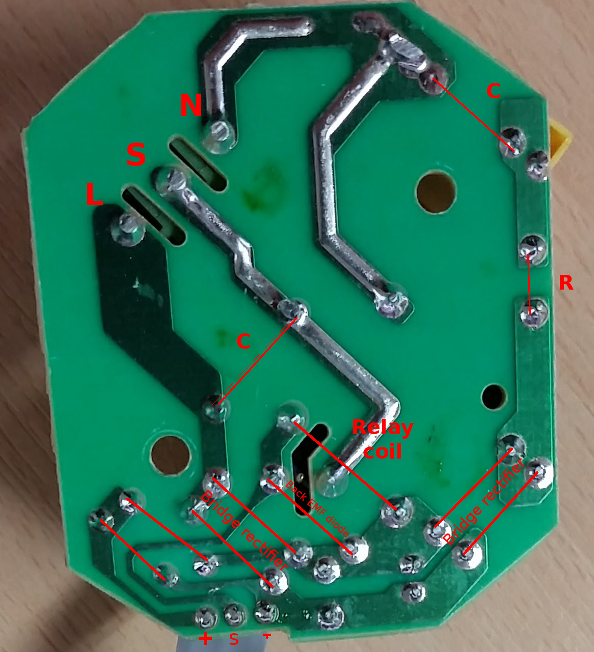
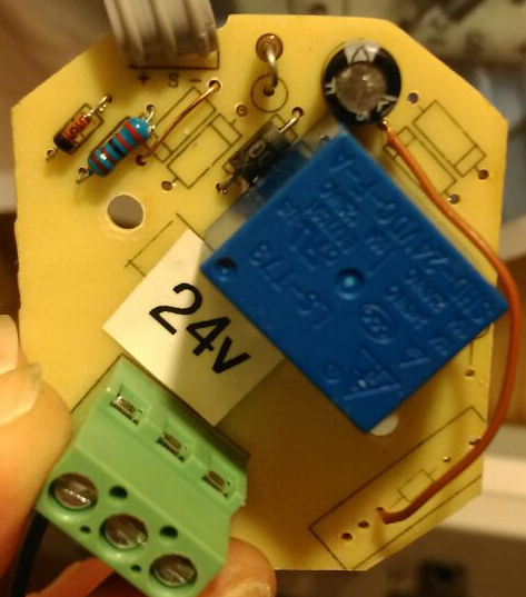
The design of this one is actually more complicated than we’ve seen previously making use of zenner diodes to drop the +24v DC to 5v for the front panel PCB.
Thanks once again to Malc who eventually gave up trying to make this design work and posted me three up to look at, I shall enjoy the beer on you mate 😉
Hack on!
Ian
Sorry for asking, but to be sure.. The red lines, are those bridges that need to be soldered? Do you have a picture of the finished back?
How are your other sensors holding up? Do you have them installed in your house and in use? Do you recommend them? I’m building a house with Loxone and would like to install these sensors in every room.
Hi Ruben,
No, the red lines were just a way of indicating the original components. On this design, there are two wires top side that need adding once the components you don’t need have been removed.
One of obvious on the above picture, the other is a little harder to spot, small copper wire next to the resistor.
In terms of using these, I still have the two I hacked sitting on the bench sadly so I can’t comment on how well they work. I did have one wired up pre-hack and it worked well.
Hope that helps!
Ian
I ordered one off eBay in the US and it was 99% the same as this model, with the exception of a fuse in between L & the capacitor connected to L. I follow your pictures exactly, then when that didn’t work, I removed the fuse and then instead of running the wire (the red one in your picture) from the ex-capacitor hole to the ex-diode hole, I started it at the ex-fuse hole.
It seems good, using a voltmeter I get 24V on every connection except the output from the relay. No matter how much movement I make, the relay output is always 0.
There was one thing I found concerning: I put my voltmeter on the PIR chip and all of it’s pins are receiving/sending 24V, but according to the data sheet the MAXIMUM voltage for the chip is 5V. I’m worried maybe I burnt the chip, but the fact that it’s sending voltage back out makes me wonder. Perhaps the instructions here removed too much? Does anyone have it working on this design? Would it help if I posted pics (don’t have time to take it apart again right now)?
Thanks!
Joe