If you haven’t seen the space recently, and are curious about how many abandoned laptops are scattered around (Surprisingly, not as many as last year) take a look at https://lamm.space/about/ for updated images of the space, and the new PCs, 3D printers and equipment.
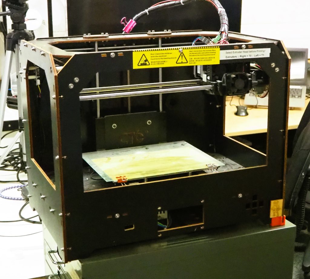
We have also been given a very kind donation of a dual extruder 3D printer. It is a bit dusty, but think of the possibilities!
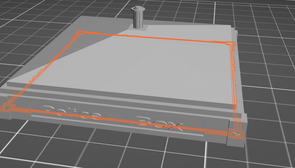
In the third post of the month/night after a cabinet and a Google hat I wanted to quickly talk about Prusa Control. Prusa Control, for the uninitiated, is a cut down version of the, very useful and powerful, Slic3r software for the Prusa printers.
Prusa love Slic3r and there is no reason to doubt it. They build a custom profile for the software and make sure it is shipped and linked across their brand. however they note that it can be over-whelming for beginners. That’s where Prusa Control comes in.
Prusa Control is aimed at ease and speed and with just settings for the Prusa 3D printers and there is something lovely about that. I have installed the beta and used it for a first print in my new cabinet.
It worked really well.
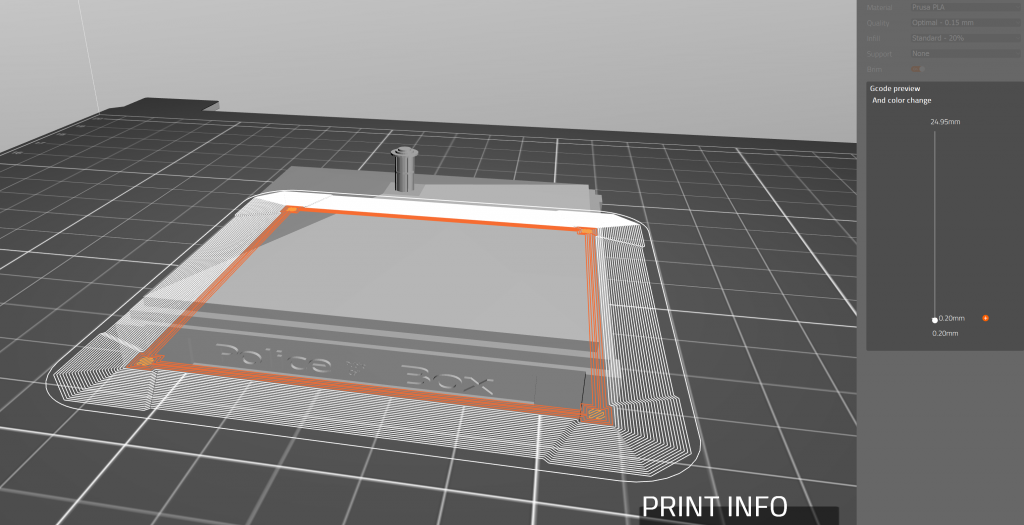
In fact I would say close to perfect. I printed with a brim and with loose settings (.2 at 15% infil for speed and ease) and I got a near perfect print with good bridging and detail and a wonderful layer height that is regular with no breaks or interrupts. The brim was light and they clearly had taken care to make sure it was a well printed but easy to remove printing support.
So for new users and for experienced users wanting to cut out the interface and get straight to the printing then it is worthwhile having Prusa Control next to Slic3r in your toolkit.
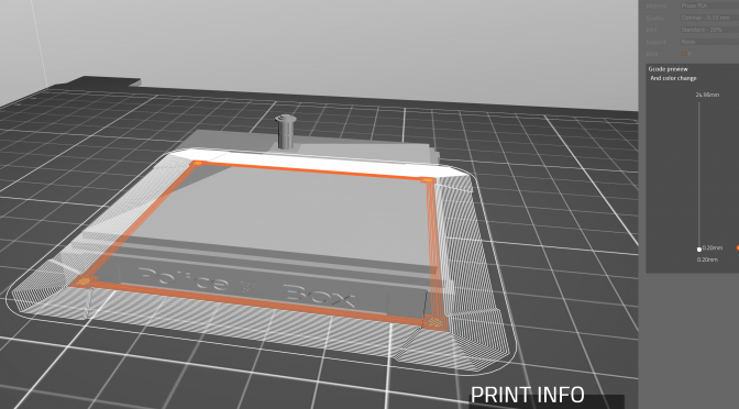
I also liked how smooth the layer height display worked after generating which is very quick and efficient.
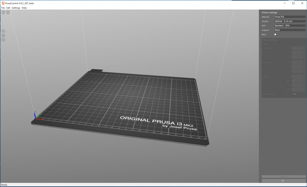
A very clean and easy to understand interface greets you on opening, seriously the controls on the side are all you have to deal with, this is minimal and almost perfect
Easy to understand layer height control
One of the prettiest and nicely printed brims I have ever worked with
I haven’t managed to get to the Space much in the last couple of months (again! – though at least I did my duties as a director, such as making some posters (see another blog to come soon) and attending meetings doing admin etc.) mostly due to summer holidays and the pressures of family life. However home projects haven’t stopped and I have a couple of blogs to talk about what I have been up to on the home front.
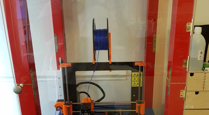
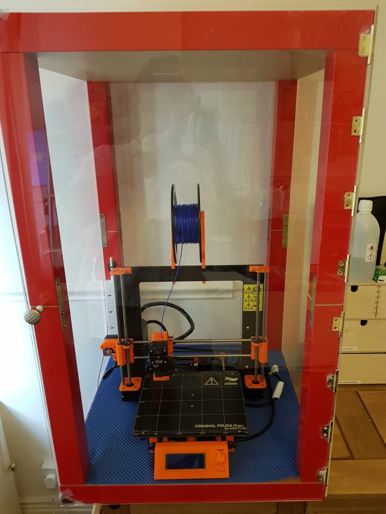
The first of these is all about my 3D printing cabinet. I was gifted a 3D printer (Prusa i3 Mk2 that I constructed with the affable TBSliver) detailed in a video to come soon. It has been working well but I often have prints that lift on one side.
After some discussion, with the amiable (and affable and affordable) TBSliver we decided it could be the drafts in the room. So again from a suggestion by the amazing TBSliver I decided to build a cabinet to hold my printer. To do this I used:
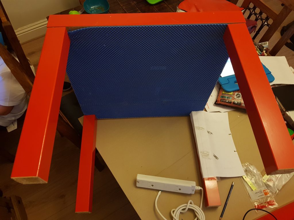
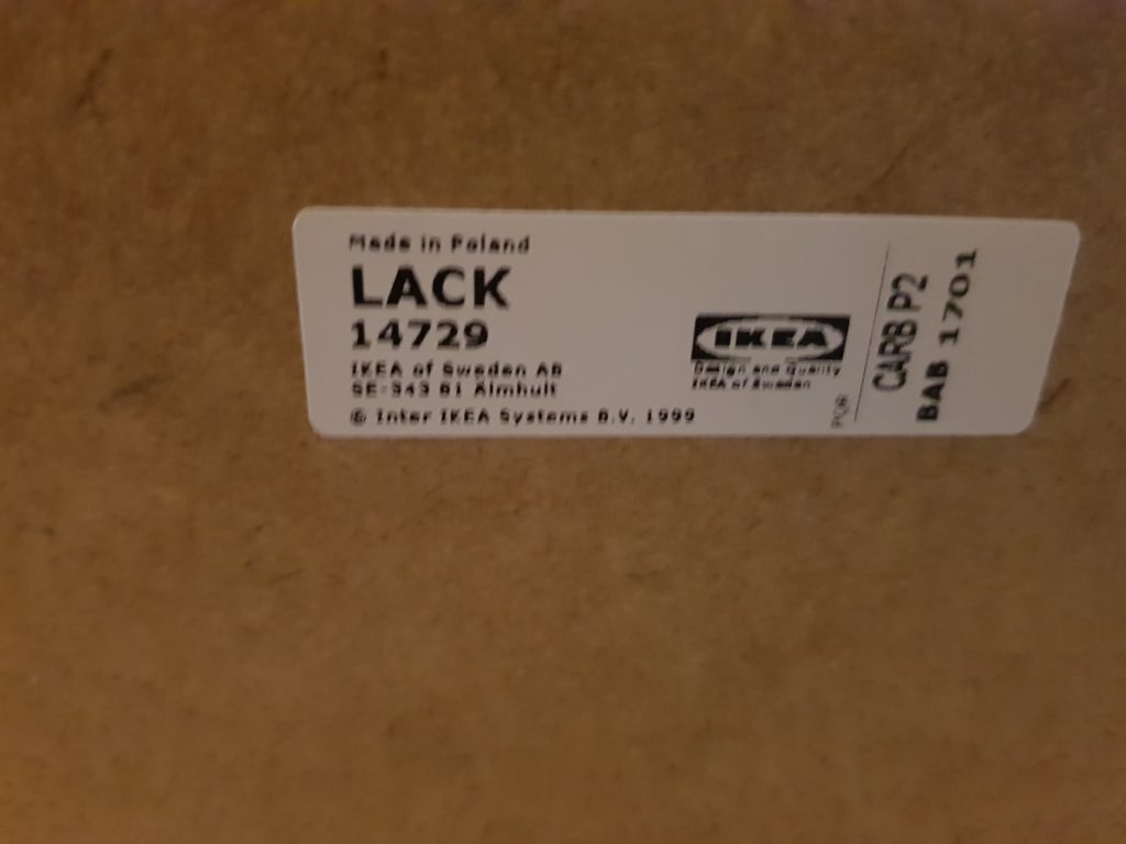
Two tables from IKEA – the well known LACK tables at £5 each (£10)
Two packs of cabinet hinges from B&Q at £4 each (£8)
One pack of straight braces from B&Q at £4 (£4)
One small knob from Wilkinsons (£2)
Some grip surface – spare piece that I had in my workshop
Screws, Superglue – all from other projects
Two magnets recovered from a hard drive that was dismantled
One 4 bar extension from Wilkinsons (£3)
Cut sheets of 3mm clear perspex with holes in three pieces for fixing (£60 including all cutting and delivery from the Plastic Man).
Total cost: £87
This might seem like a high sum, especially the perspex, but they are large sheets at 890mm by 550mm x 4 – and close to £12 for delivery. The actual sheets were £12 or so each and were delivered on time and well cut and transported so a bargain if compared to similar online retailers. I heartily recommend the service.
Construction was simple:
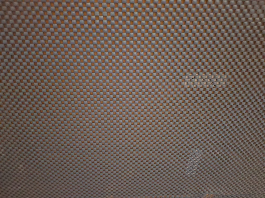
Glue down some non-slip matting
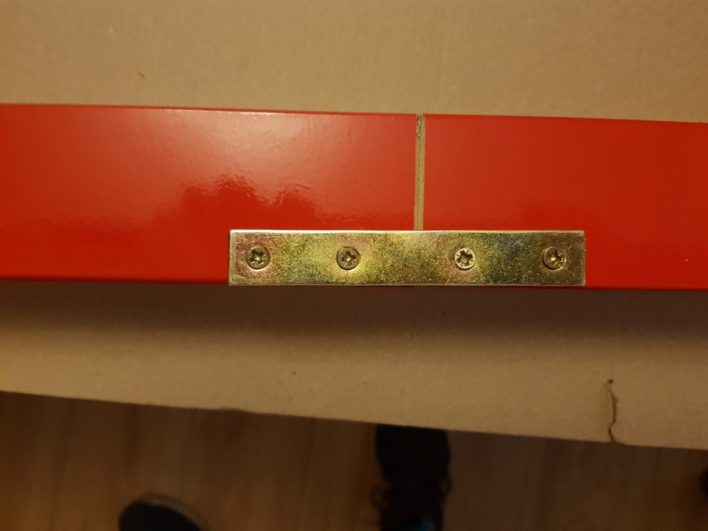
Align the two tables and fix together with straight braces (2 on each leg)
Align the pre-drilled screw holes of the perspex and carefully screw down (do not over-tighten as perspex will crack
Glue hinges to the perspex door and leave to cure for 24 hours
Screw door to frame.
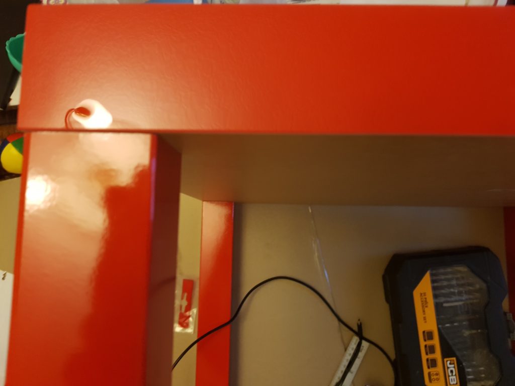
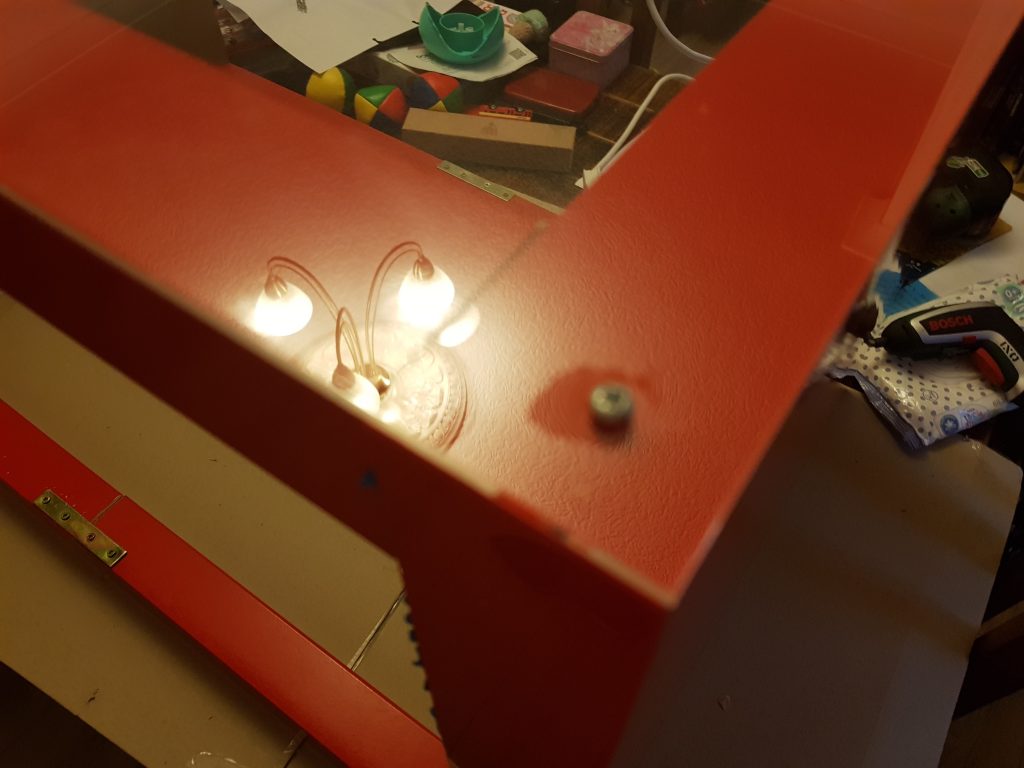
Forget that you need a hole for the knob!**
My only issue is that the tables were a little flimsy and not very accurately made (a <1mm difference in legs from the cut and glazing process) which coupled with some slight inacuracies of the angle of screw holes can give ever so slight deviance in the build. However for £5 it is a small price and easily correctable once we bolted the whole frame together.
The finished box is quite pretty (IMO) and site nicely on the side dresser where I have my specialist tools and electronic knick knacks. in the utility room of the house.
Once again a big thanks to the wonderful chap who is TBSliver for all of his help, advice, support and praise, greatly appreciated. LAMM members are wonderful creatures.
Pictures below.
(** I solved this issue with the careful use of a soldering iron)
Lining up with a steel ruler and drilling holes with my drill
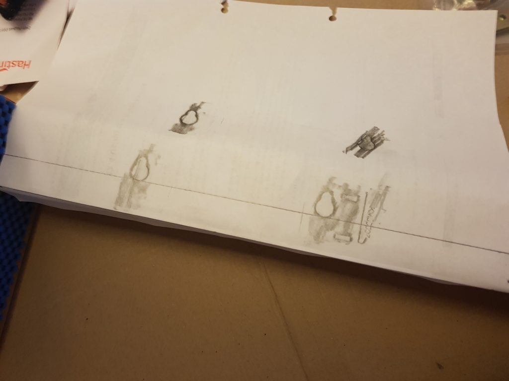
Non slip matting in place and using a quick template for the mounting of the internal power strip
Close up of non-slip matting
Here’s that template again, who needs expensive tools when a pencil and paper trick is shown to you
EU made card tables that are firmer than the price warrants
The bracing of the legs
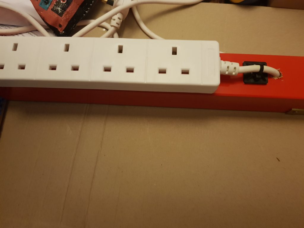
Fitting the power internally so the cabinet has internal source.
Carefully tighten down the corners – so brightly reflective
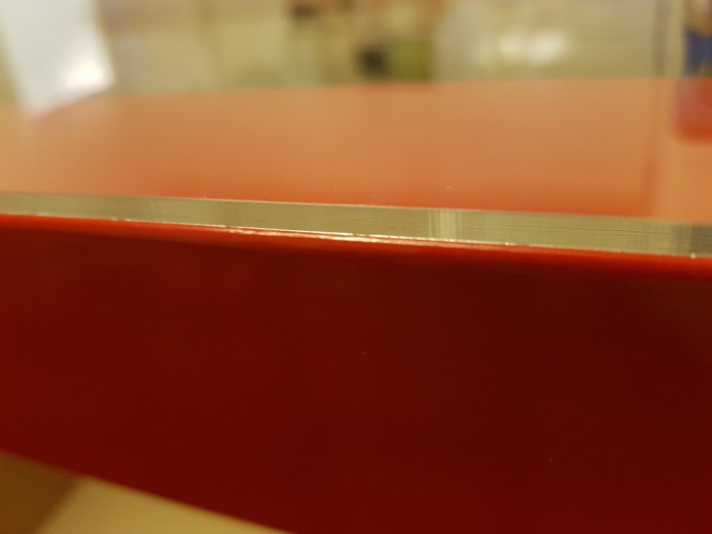
Close up of the fit – nice and snug
The finished cabinet – I should be able to fit some tool and equipment bays at the top next
For a while now, I have been trying to make a dry box for storing 3D printer filament, having had problems with a reel of ASA filament becoming damp and the prints made from it coming out pitted and fragile. The first idea I tried was to use silica crystal cat litter as a dessicant in a sealed box. I bought a transparent storage box with a rubber seal and a packet of silica cat litter, as well as a cheap digital hygrometer / thermometer. Then I burned some holes in the lid of a plastic fast food tray with a heated skewer, and put the cat litter in the tray. Finally I put the tray, the hygrometer and the filament into the storage box and sealed the lid.
I left the cat litter in the box for a full day, and the humidity reading actually increased slightly from 55% Relative Humidity (RH) to 59% RH. This was at a nearly constant temperature varying from 24 °C to 23.7°C. The increase was within the error range of the meter but not the significant drop I had been hoping for.
The next thing I tried was to crush the crystals using the somewhat crude method of wrapping them in a strong piece of cloth and bashing them with the end of a brick, to see if this would increase the surface area of the crystals and make them absorb water better. This didn’t work so well as silica crystals are quite hard, and it also didn’t make them any better at drying the air in the box.
I suspect that the reason the cat litter didn’t work is that even though silica does absorb water, the granules you get in the sachets that come with electronic devices are prepared in a way that makes them highly porous and able to absorb atmospheric moisture, whereas the silica that is used as cat litter is designed to absorb liquid water so they make it out of solid crystals.
At this point I did a bit of research online and found this web page about drying mushrooms. It has a pretty good summary of the three main substances used as dessicants, how effective they are, and how to use them. In order of increasing effectiveness, they are silica gel, which will bring the humidity down to about 40% RH, calcium chloride, which is what is found in home dehumidifiers and can bring the humidity down to below 25% RH, and calcium sulphate, which is the strongest of the three and according to that page can lower the humidity to a few percent RH.
As it says on that page, calcium sulphate is the same chemical substance as plaster of Paris. This is a substance which attracts water strongly into its crystal structure, and can come in several forms depending on how much water it has absorbed: hydrated (fully saturated with water), hemi-hydrated (partly saturated), and anhydrated (no water at all). Plaster of Paris is the hemi-hydrated form and can be bought quite cheaply from craft shops.
The simplest way to make powdered plaster of Paris into a dessicant would be just to heat it in an oven to drive the water out of it, let it cool in a sealed heatproof container, and then put it into the dry box. This would probably work okay, but it would have the problem that air wouldn’t be able to percolate through the powder easily so it might take a long time to dry the air in the box.
I decided instead to try to make it into granules, thinking that they might absorb the water vapour better. The rest of this post describes how I did this.
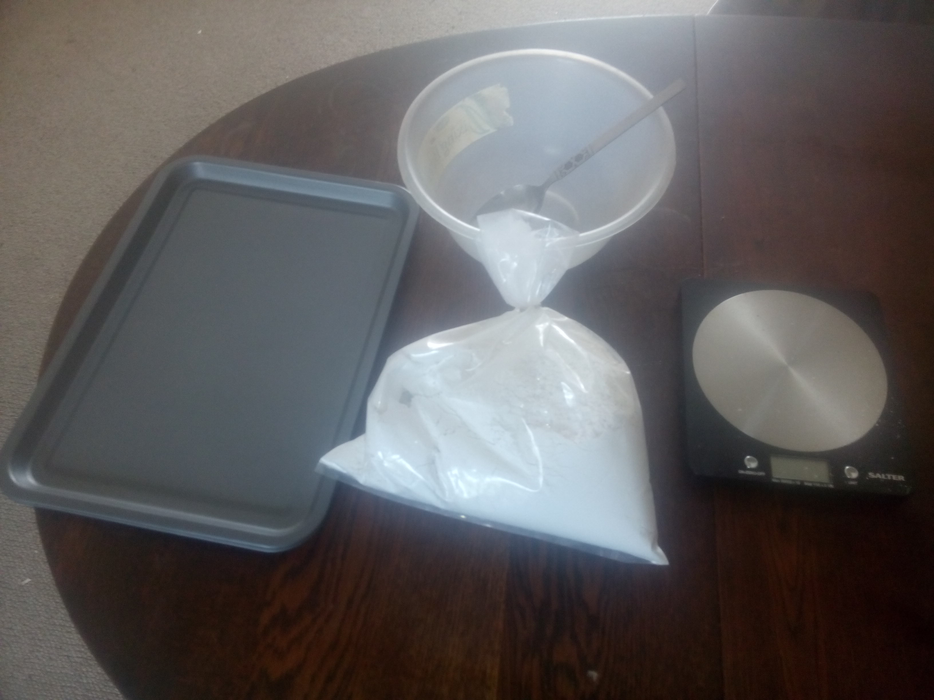
Some of the equipment I used to make the granules.
The photo above shows some of the equipment I used to make the granules – two non stick baking trays, a bag of plaster of Paris, a mixing bowl and metal spoon, and a kitchen weighing scale. I also ended up using a couple of large glass jars, some rubber gloves, two plastic bags, a piece of heavy cloth about 40 cm square, some string, a pint glass of water, and a brick.
The first thing to do was to measure out enough plaster to fill the baking trays in a thin layer. You may want to wear rubber gloves for this as plaster is slightly irritant. I did this by just spreading it out in the trays to what looked like a reasonable depth to be able to break it easily once it had set.
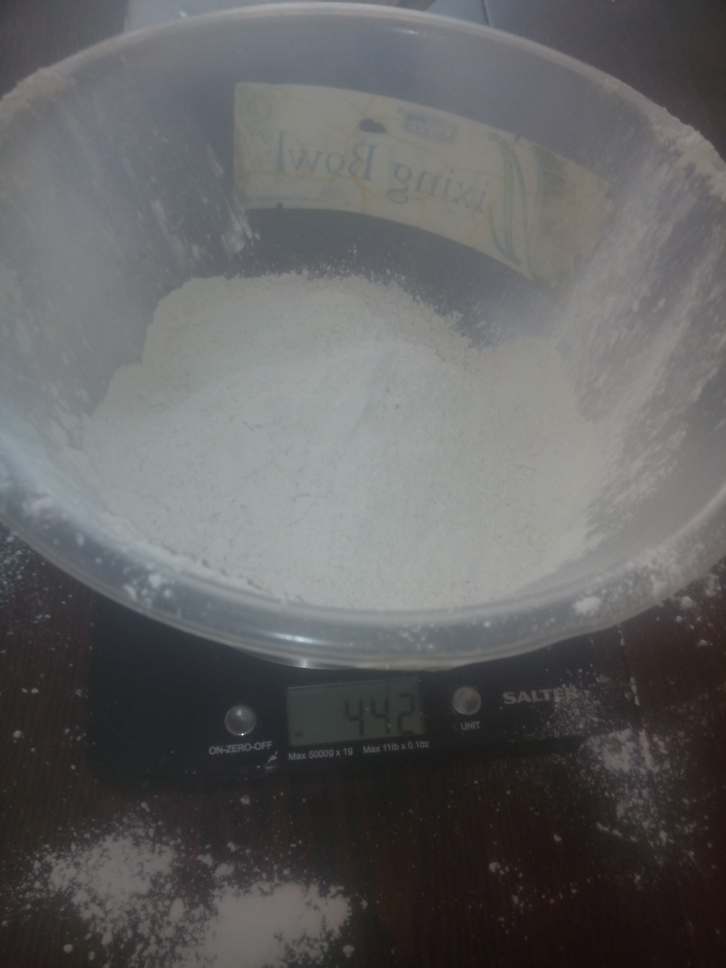
Then I put the mixing bowl on the scales, zeroed them, poured the plaster into the bowl and wrote down the weight – 442 g.
Weighing the plaster of Paris
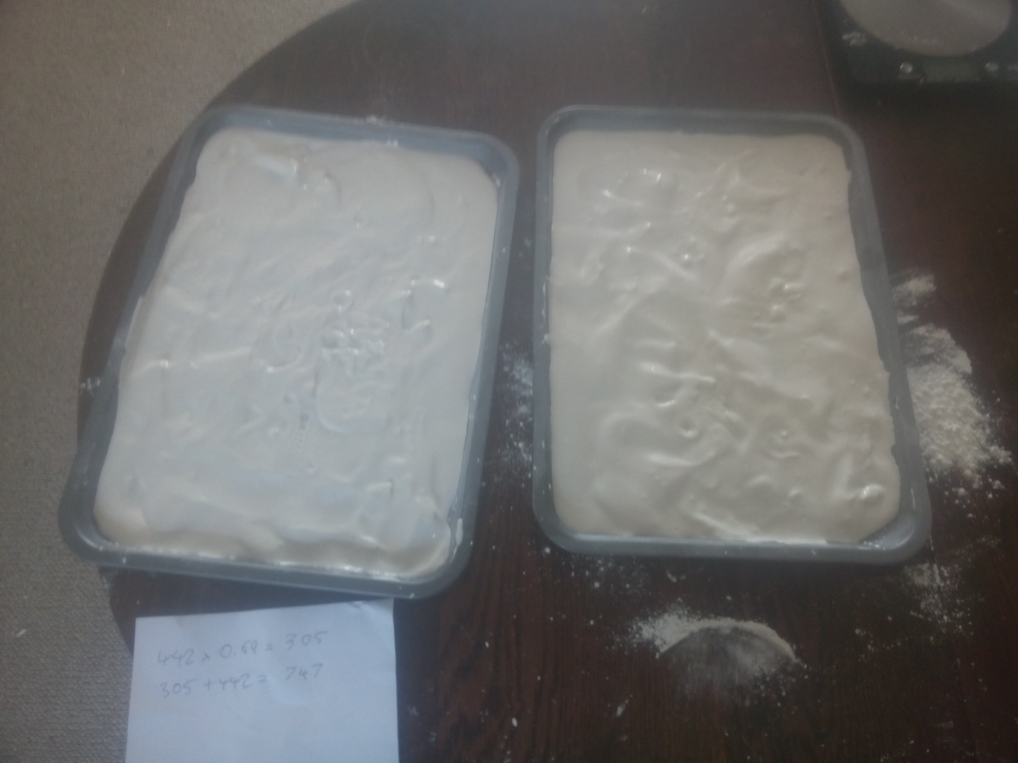
You make up plaster by mixing it with water in a ratio of 100 : 69 by weight. This makes 305 g of water, which makes a total of 747 g in the bowl. I then made a bit of a hole in the middle of the plaster and poured water in until the weight was (about) 747 g. Then I mixed it with the spoon until it was smooth, and poured it into the two trays in roughly equal amounts.
Liquid plaster in baking trays
I then allowed this to dry for a while (the instructions on the plaster say 6 – 10 minutes). The next thing was to take the plaster out of the trays and break it into granules.
To do this, I first put the trays inside a large plastic bag and turned out the sheets of plaster. These came out quite easily.
Turning the plaster out of the trays
Having done that, I then put the bag inside another bag, broke up the plaster sheets a little bit by hand and then wrapped the bags inside the cloth square with a piece of string.
Plaster fragments inside bags
Plaster and bags wrapped in cloth
The next thing was to bash the bag with the end of a brick until it seemed like the plaster sheets were all broken up. Then I took the newly broken granules out of the bag, laid them out in the baking trays, and baked them in the oven at 230°C for two hours.
Plaster granules ready for baking
I left the trays on the hob for a couple of minutes to cool down a little, then poured the granules into the large glass jars to cool properly.
Plaster granules cooling in jar
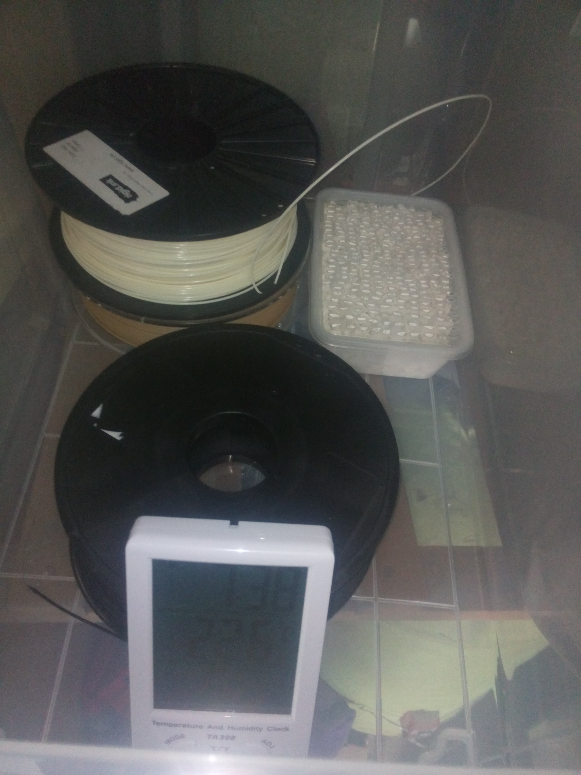
Once they were cool, I put them into the plastic tray with the holes in the lid and sealed this in the storage box with the hygrometer reading visible through the plastic sides.
Plaster granules, hygrometer and filament spools inside the dry box
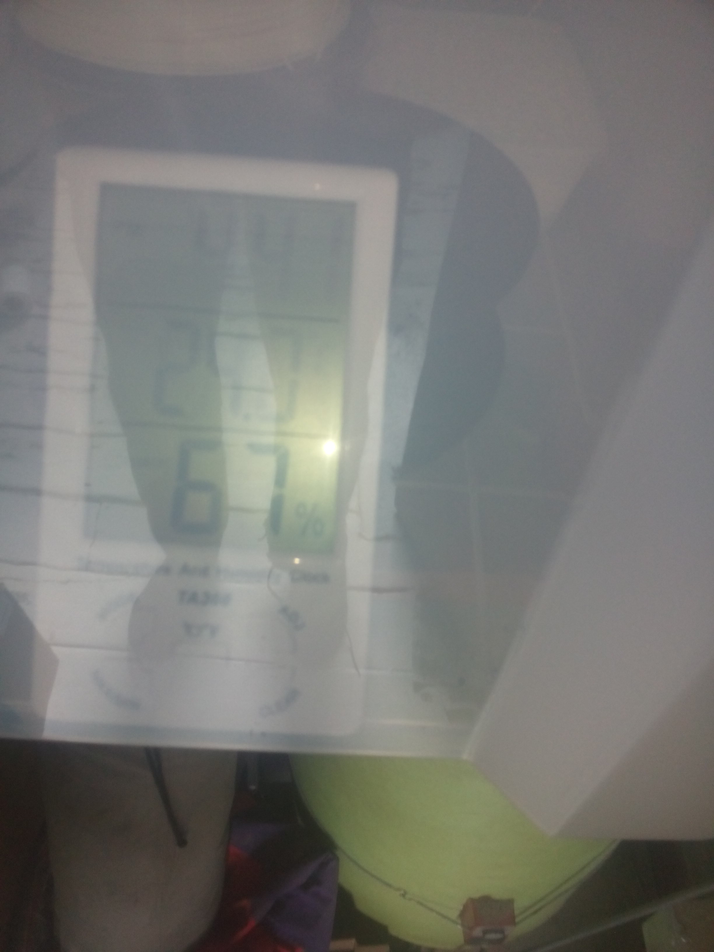
The box sealed with the hygrometer reading showing
Finally it was time to see if the granules were going to work. I wrote down the time and relative humidity for the next few hours, and watched the humidity fall from 62 % RH at 16:42 to 27 % RH at 23:04. It fell quite fast at first, going down to 38% by 18:03, and then slower after that. Whether it will get all the way down to the level of a few percent that the web page I referred to above says you can acheive using calcium sulphate, I’m not sure yet, but I’m pretty pleased with this result, as it is below the level that is supposed to be acheivable using silica gel.
One test I would like to do is to open the box again in a day or two, let the air mix, and then see if the humidity drops as fast the second time, to get an idea of how much drying capacity this amount of dessicant has. If I get around to this I’ll post an update in a comment.
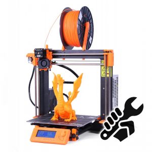
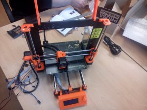
We recently decided that we needed a new 3D printer for the space, given that one of the members who had been kindly lending us their printer (thanks Vic Harkness) has moved away, and the other main printer we have, which is also lent by a member, is currently not working. We’ve had several people joining recently because they wanted to do 3D printing, so we decided it was important to have a printer that was owned by the space, which we could maintain collectively. We settled on a kit of the Prusa i3 printer from prusa3d.com (see image, which is copied from their site).
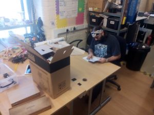
The box arrived just in time for our Wednesday open meeting last week, and was eagerly unpacked. As several other blog posts I’ve read have said, it was immediately obvious that a lot of care had gone into the design and also the packing of this kit. The outer box was pretty substantial and all the parts were well organised and neatly packed inside smaller boxes. The 3D printed parts and smaller fixings were put in plastic bags labelled by the assembly they belonged to, which makes it easy to work through the assembly manual and know that you have all the parts for the current step to hand. There were even screen printed labels on the motors to say which axis they belonged to.
Starting unpacking
Due to peoples’ time commitments, we had to wait until Monday morning to make a start on building the printer. The building was done by Gustavo Carreno and Andrew Baxter.
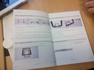
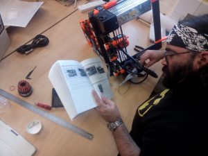
The assembly manual was pretty clear and helpful, with colour coded photos of the tools needed and the 3D printed parts used in each step. There is an online version available on the prusa3d website, which people are advised to consult in case of problems. The online version is also useful if you can’t make out the details in some of the pictures.
The assembly manual
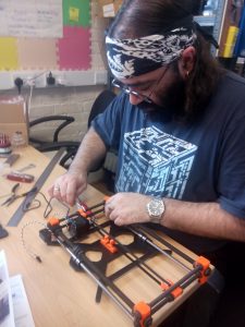
The main thing to say about the build process, apart from a few small points I’ll make later, is that it’s pretty much just a question of preparing yourself for a number of hours of careful assembly work, following the instructions step by step. (We did it over 3 days, but two of them were half days. Some people have done it in an afternoon, but expect to take longer if you’ve not built a printer before). None of the steps are that difficult in themselves – you just need to keep paying attention to what you’re doing. I would suggest that it might be worth at least skim-reading through the instructions for each stage of the assembly before you work though and build that stage, just to get an idea of where you’re going with it. However we mostly just worked through in order and didn’t have any real problems.
Gus working on the Y-carriage
One thing that we did a bit differently from the manual, which I think is worth passing on, was to do with aligning the y-axis stage. If you look at the assembly manual, on page 6 of the version I have, under ‘Step 6 – Fully assemble the Y-axis stage’, it points out that it’s important to get the axis perfectly rectangular at this point, or you’ll have trouble calibrating later. One thing here is that it’s probably better to get a reasonable alignment here, but wait until a few steps further on before you really try to get it precise. This is because in the following steps you will be fitting the stage to the main frame, and also to the smooth rods that carry the Y-carriage, so some of the dimensions may need to be changed.
Another thing is that the automatic calibration process is actually pretty good, at least at aligning the X and Y axes, so the kit should be reasonably forgiving of small alignment errors. In other words don’t do what we did and spend a whole morning trying to get the Y-stage perfectly aligned, only to discover that (a) as I’ve said above we then needed to change things again, and (b) the automatic calibration takes out most small errors anyway!
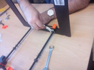
You might also like to try the following trick for getting the frame rectangular and level. Do this after you’ve fitted the length of the carriage to the 8mm smooth rods, as in step 10, but skip step 9 (‘tighten the sides to the y-axis stage’) for now. In other words, at this point you should have fully assembled the Y-axis stage, and adjusted the length of it to the smooth rods.
Aligning the Y-axis stage
What we did next was to start by loosening all the M8 nuts on the Y-axis stage, so that it could adjust in width (but not length) to fit the main frame. Next we slid the front end of the stage into the slots in the frame, setting the width. Then, which is what is different from in the manual, we moved two of the loose M10 nuts which will eventually hold the frame in its final position all the way down the threaded rod until they could be used to clamp onto the frame, and used a spanner to tighten them, as shown in the picture above. The idea was that with the M8 nuts still loose, this would force the two M10 rods to be close to perpendicular with the frame and thus make the stage rectangular. Then at this point we carefully tightened all the M8 nuts.
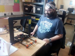
Finally we took the Y-axis stage out of the frame and used a ruler to check all of the widthways and lengthways dimensions at each end, and made final adjustments as appropriate. Whether this is better than what the manual suggests, I’m not sure, but we did okay when it came to running the automatic calibration.
Gus admiring the completed Y-axis
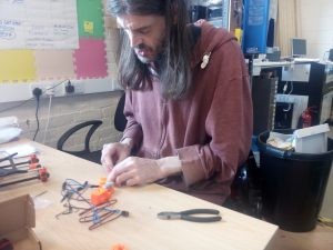
The X and Z axis assemblies were pretty straightforward – as I said above just a case of working through the instructions carefully. Tightening the X (and Y) axis belts was a little bit tricky – the knack seems to be to make a loop of about the right length held in a pair of pliers, then keep trying it against the belt holder and if it’s too loose, keep moving it tighter one tooth at a time and trying it again.
Andy working on the extruder assembly
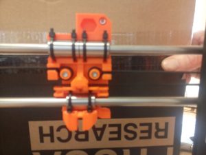
Don’t do what we did and forget you can slide the whole X-axis down along the Z-axis to get to the back of the X-carriage and work on the belt. You might also like to pause at this point and admire the skull-like appearance of the back of the X-carriage!
Yes the X Carriage really does look like a skull from behind
The extruder was also pretty straightforward to assemble. Managing all the cables going from the extruder to the electronics was tricky, but we did all right following the instructions step by step. Using a piece of 3mm filament to stiffen the cable bundle is a neat trick.
Gus working on the cable management
After the extruder, it was time for the LCD assembly. The main thing here was to be careful not to crack the circuit board of the LCD while getting it into the plastic frame.
LCD assembly completed
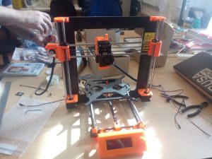
Next was the power supply and heated bed.
With the power supply and heated bed assembled
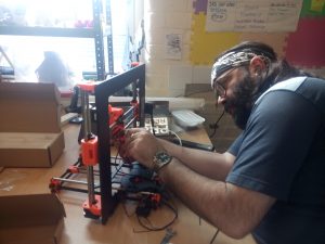
Finally, it was time to wire it all up – the electronics assembly. One difficulty here was that because all the parts on the electronics housing are black, it was hard to make out what is what in the printed photos. The online manual is useful here. Getting all the cables to the right place needs a bit of care, as many of them take the same fittings. However if you just follow the manual and double check each stage of the assembly you should be okay.
Gus wiring up the electronics
Finally, after 3 days work, on and off, we had a fully assembled printer. At this point, we had to break while I (Andy) went to an un-missable appointment and had lunch. Gus chivalrously waited for me to get back before we did the grand turn on.
Somewhat to our surprise (mine anyway), it passed all its tests first time. The calibration took a while but went all right (although the first time we did it, the printer seemed to lose the settings when we turned it off and we had to re-calibrate). It was interesting to see how it first scanned roughly around the points where the calibration markers were, and then homed in on them more precisely.
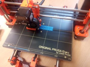
Then it was time to do the first print. There are several prints on the SD card that comes with the printer – we chose the Prusa logo, which came out nicely.
Printing out the Prusa logo.
I don’t want to spend too much time on a review of how the printer works – this post is meant more as a guide to the build process rather than a review. Maybe one of us can do a review of the printer when we have a bit more experience using it. However, my first impressions are very positive. The prints are as good as or better than the Lulzbot TAZ we were using before, the calibration system is very neat indeed, and the LCD controls are easy to operate.
In summary, I’d say that this is a well designed and neatly packaged kit which anyone with a reasonable level of mechanical aptitude should be able to put together over a couple of days without too much trouble.